Exploring the FlexRadio SmartSDR Ethernet API with a Raspberry Pi - by AB9A
Experimental GTK3+ GUI
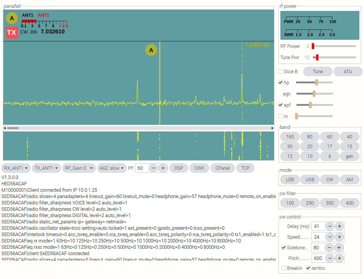
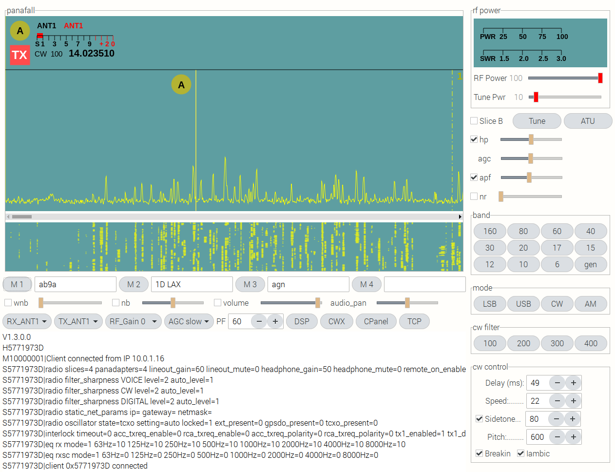
The screenshot above is an experimental standalone control surface for my FlexRadio 6600 transceiver, using a subset of the SmartSDR Ethernet API, running on a Raspberry PI 4 SBC.
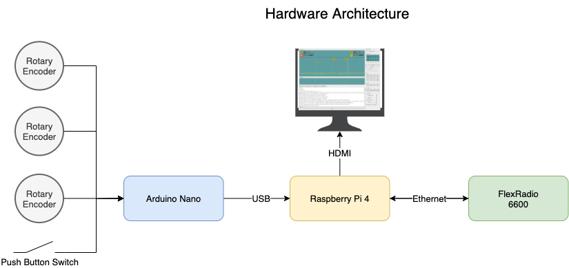
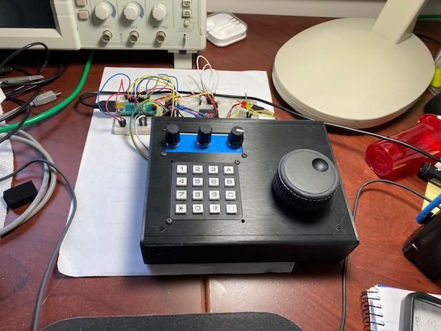
The hardware is configured as in the diagram above. The CW Key, Mic and headphones are connected directly to the radio. The keyboard and mouse are connected to the Raspberry Pi. Physical knobs and switches are captured by the Arduino Nano and sent to the Raspberry Pi over a USB cable.
Features implemented so far:
One Panadapter / Waterfall display ( Panafall ):
- 1 or 2 Slice Receivers
- Right Mouse Click to select active slice receiver
- Active Slice Receiver is Yellow, non-active is Red
- Dashed vertical tuning Cursor, with frequency display, that follows mouse pointer
- Mouse click to tune the active slice receiver, at cursor position
- Mouse Wheel fine tuning of active slice receiver
- Physical VFO Tuning Knob for active slice receiver
- Overlay Slice Receiver filter bandwidth on spectral display
- Physical tuning knobs for filter upper and lower frequencies
- Mouse Click the Flag TX button to select which slice is the transmit VFO
- Flag for each slice receiver that displays:
- Slice RX Antenna
- Slice TX Antenna
- Slice ID (A/B)
- Slice TX Selection
- Slice S Meter
- Slice Mode
- Slice Filter Bandwidth
- Slice Frequency
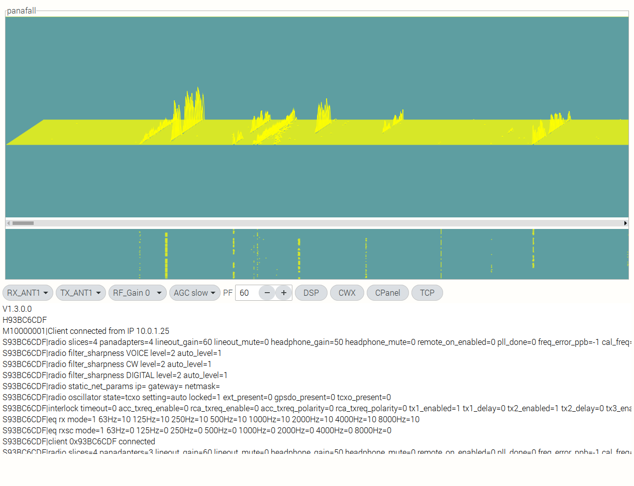
- Horizontal Scroll Bar - Scrolls the Panafall Window across the selected band
Horizontal Control Bar, beneath the Panafall:
- Drop down RX Antenna selection, for the active slice receiver
- Drop down TX Antenna selection, for the active slice receiver
- Drop down Gain selection for the SCU
- Drop down AGC Mode selection
- PF +/-, sets the Panafall horizontal pixel bandwidth (zoom)
- DSP Button, show / hide the DSP Control Bar
- CWX Button - show / hide the CWX Control Bar
- CPanel Button - show / hide the right side Vertical Control Panel
- TCP Button - show / hide the scrollable window that displays TCP Messages from the radio (lower left)
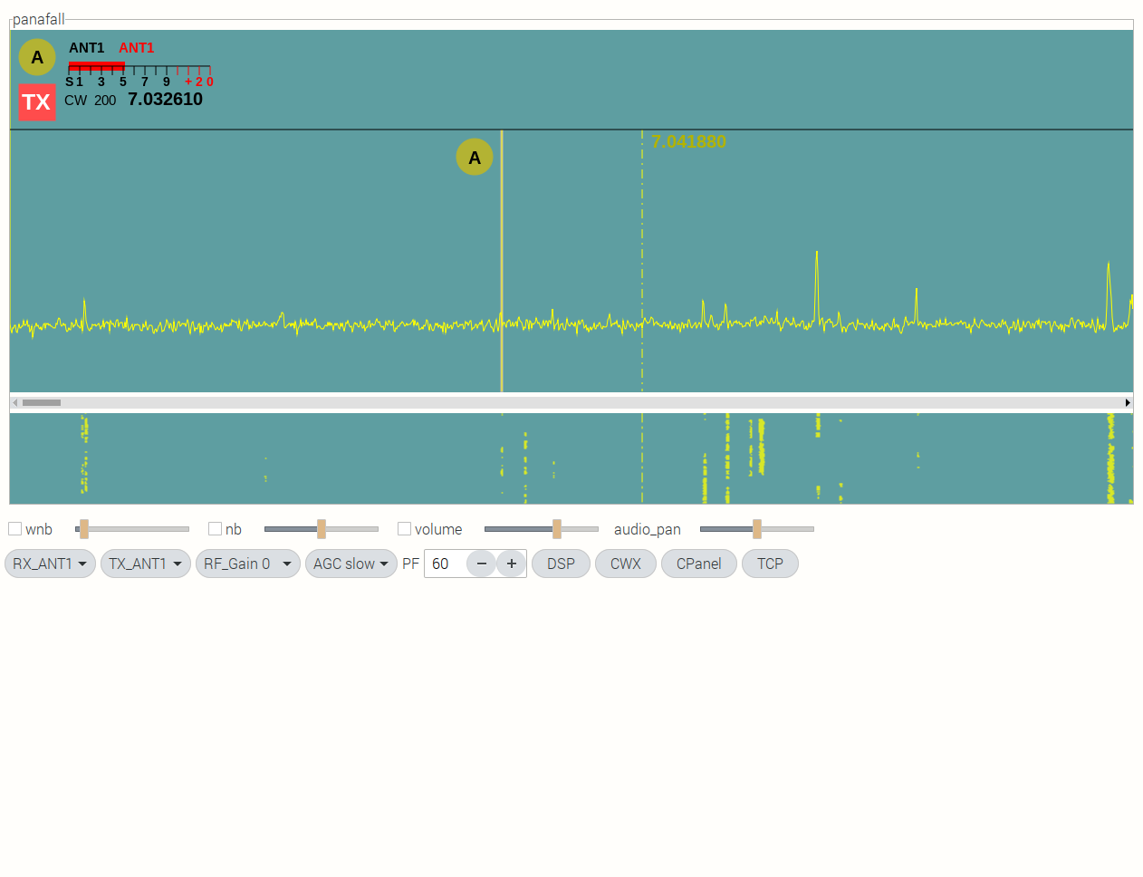
Horizontal DSP Control Bar, beneath the Panafall:
- WNB on/off and level
- NB on/off and level
- Audio mute and level, for the active slice receiver
- Audio pan control for the active slice receiver
Horizontal CWX Control Bar, beneath the Panafall:
- Message 1 - text field and send button
- Message 2 - text field and send button
- Message 3 - text field and send button
- Message 4 - text field and send button
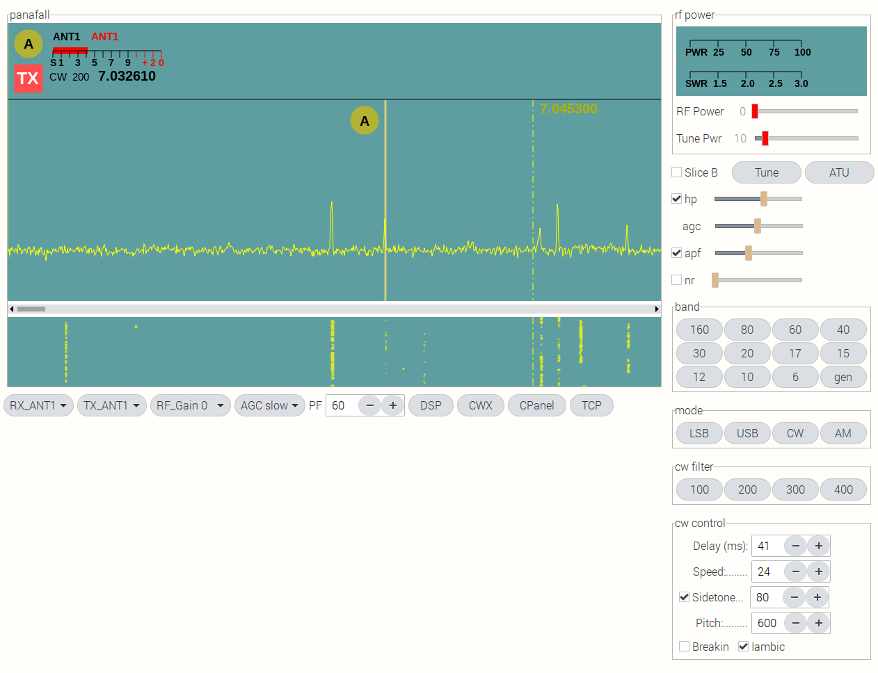
CPanel - Control Panel on right side:
- Power level meter
- SWR level meter
- RF Power level control
- Tune Power level control
- Slice Receiver B add/remove button
- Tune on/off button
- ATU Start button
- Headphone on/off and level
- AGC-T level for the active slide receiver
- APF on/off for the active slice receiver
- APF level for the active slide receiver
- NR on/off for the active slice receiver
- NR level for the active slice receiver
- Band selection button pad
- Mode selection button pad
- CW filter selection button pad (visible in CW mode)
- USB filter selection button pad (visible in USB mode)
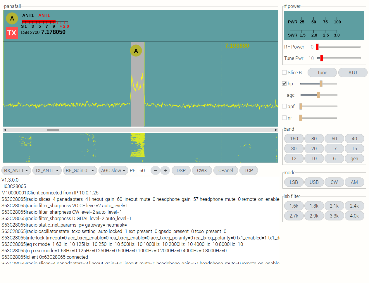
- LSB filter selection button pad (visible in LSB mode)
- AM filter selection button pad (visible in AM mode)
- CW Control Panel (visible in CW mode):
- Delay +/- buttons and number field
- Speed +/- buttons and number field
- Sidetone on/off, +/- buttons, and number field
- Pitch +/- buttons and number field
- Breakin on/off
- Iambic mode on/off
Physical Control Surface:
- All controls switch to the active Slice
- 3 Programmable encoder knobs (expandable to 6)
- VFO Tuning Knob
- 16 key keypad
- Direct frequency entry
- Change the Active Slice by pressing the A or B keys
Screen Shots:
- WNB on/off and level
- NB on/off and level
- Audio mute and level, for the active slice receiver
- Audio pan control for the active slice receiver
Horizontal CWX Control Bar, beneath the Panafall:
- Message 1 - text field and send button
- Message 2 - text field and send button
- Message 3 - text field and send button
- Message 4 - text field and send button
CPanel - Control Panel on right side:
- Power level meter
- SWR level meter
- RF Power level control
- Tune Power level control
- Slice Receiver B add/remove button
- Tune on/off button
- ATU Start button
- Headphone on/off and level
- AGC-T level for the active slide receiver
- APF on/off for the active slice receiver
- APF level for the active slide receiver
- NR on/off for the active slice receiver
- NR level for the active slice receiver
- Band selection button pad
- Mode selection button pad
- CW filter selection button pad (visible in CW mode)
- USB filter selection button pad (visible in USB mode)
- LSB filter selection button pad (visible in LSB mode)
- AM filter selection button pad (visible in AM mode)
- CW Control Panel (visible in CW mode):
- Delay +/- buttons and number field
- Speed +/- buttons and number field
- Sidetone on/off, +/- buttons, and number field
- Pitch +/- buttons and number field
- Breakin on/off
- Iambic mode on/off
Physical Control Surface:
- All controls switch to the active Slice
- 3 Programmable encoder knobs (expandable to 6)
- VFO Tuning Knob
- 16 key keypad
- Direct frequency entry
- Change the Active Slice by pressing the A or B keys
Screen Shots:
- Direct frequency entry
- Change the Active Slice by pressing the A or B keys
The controller uses the radio's persistence property. And, parses the radio's TCP messages to initialize the controller to the state of the radio.
The controls that are common to both slice receivers are shared, to conserve window area. They are connected to the active slice receiver. And, they remember their settings when switching between slices.
Essential Documentation:
- Programming the API: A Primer by G3WGV
- The FlexRadio SmartSDR Ethernet API Wiki
- The FlexRadio Community
- Generating a Pan Adaptor and Waterfall Display
- Socket Programming HOWTO
- C and GUI Programming by Simon Long
- ZetCode GTK+ Tutorial
- PYSimpleGUI
- GTK3+
Getting Started:
The first step was to download and study "Programming the API: A Primer by G3WGV". John Linford has done the heavy lifting in breaking down the Vita-49 packet structure and explaining the basics of using the Ethernet SmartSDR API. You can find it on the FlexRadio SmartSDR Ethernet API Wiki.
If you want to plot a Panadapter and Waterfall you will want to read "Generating a Pan Adaptor and Waterfall Display" written by Stu Phillips, K6TU. Just do a search for it in the FlexRadio Community or use the link above.
The Project has basically progressed in 3 phases:
- Phase 1 - Writing software to discover and connect to the radio
- Phase 2 - Writing a Python interactive GUI tool, to study the API and learn event driven GUI programming
- Phase 3 - Writing a "C" interactive, realtime, operational GUI and USB hardware interface
Discovering and Connecting to the Radio:
Because, phase 2 required Python and Phase 3 required "C", I wound up writing Phase 1 in both Python and "C". Here are links to:
Each is an example of a linux Terminal program that:
- Discovers the radio on the network
- Parses and prints the broadcast discovery message to the Terminal
- Captures the radio's IP Address
- Opens a TCP socket on port 4992 and connects to the radio
- Reads the messages the radio sends back over the TCP port and prints them to the terminal
When you compile and run the C source code, or run the Python program, both print the same output to the Terminal:
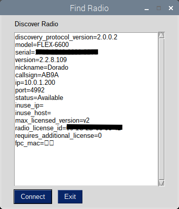
discovery_protocol_version=2.0.0.2
model=FLEX-6600
serial=xxxx-xxxx-xxxx-xxxx
version=2.2.8.109
nickname=Dorado
callsign=AB9A
ip=10.0.1.11
port=4992
status=Available
inuse_ip=
inuse_host=
max_licensed_version=v2
radio_license_id=xx-xx-xx-xx-xx-xx
requires_additional_license=0
fpc_mac=

 ************************* TCP Data ************************
V1.3.0.0
HBAAC4C0F
M10000001|Client connected from IP 10.0.1.3
SBAAC4C0F|radio slices=4 panadapters=4 lineout_gain=60 lineout_mute=0 headphone_gain=50 headphone_mute=0 remote_on_enabled=0 pll_done=0 freq_error_ppb=-1 cal_freq=15.000000 tnf_enabled=1 snap_tune_enabled=1 nickname=Dorado callsign=AB9A binaural_rx=0 full_duplex_enabled=0 band_persistence_enabled=1 rtty_mark_default=2125 enforce_private_ip_connections=1 backlight=50
SBAAC4C0F|radio filter_sharpness VOICE level=2 auto_level=1
SBAAC4C0F|radio filter_sharpness CW level=2 auto_level=1
SBAAC4C0F|radio filter_sharpness DIGITAL level=2 auto_level=1
SBAAC4C0F|radio static_net_params ip= gateway= netmask=
SBAAC4C0F|radio oscillator state=tcxo setting=auto locked=1 ext_present=0 gpsdo_present=0 tcxo_present=0
SBAAC4C0F|interlock timeout=0 acc_txreq_enable=0 rca_txreq_enable=0 acc_txreq_polarity=0 rca_txreq_polarity=0 tx1_enabled=1 tx1_delay=0 tx2_enabled=1 tx2_delay=0 tx3_enabled=1 tx3_delay=0 acc_tx_enabled=1 acc_tx_delay=0 tx_delay=0
SBAAC4C0F|eq rx mode=1 63Hz=10 125Hz=10 250Hz=10 500Hz=10 1000Hz=10 2000Hz=10 4000Hz=10 8000Hz=10
SBAAC4C0F|eq rxsc mode=1 63Hz=0 125Hz=0 250Hz=0 500Hz=0 1000Hz=0 2000Hz=0 4000Hz=0 8000Hz=0
SBAAC4C0F|client 0xBAAC4C0F connected
The printout above shows that the program did successfully Discover the radio, Open a TCP Socket, Connect to the radio and Read all of the Version, Handle, Message and Status information sent back from the radio.
The Discovery portion of the program parsed the data on spaces (" "), and added new lines (line feed), which makes the data more readable. But, the TCP data is printed raw.
After connecting the TCP Socket, the next step is to open a new UDP socket and read the radio's streaming data (spectral display, waterfall, meters etc). The streaming data rate is way too fast to view it on the terminal. So, an interactive Graphical User Interface (GUI) is needed to capture snapshots of the streaming data and format it, so that I can study it and compare it to G3WGV's tutorial.
Writing a GUI learning tool:
Being somewhat new to event driven GUI programming, I started a google search to find a GUI that would be user friendly for a beginner. What I found is PYSimpleGUI:
PYSimpleGUI websitePYSimpleGUI takes the tkinter (tk) GUI tool kit and abstracts it into an easy to understand format. So, I proceeded to write the learning tool in Python using PYSimpleGUI.
Here is the discovery window that shows on launch, once the radio is found:
When you click connect, the discovery window closes and the operational window opens:
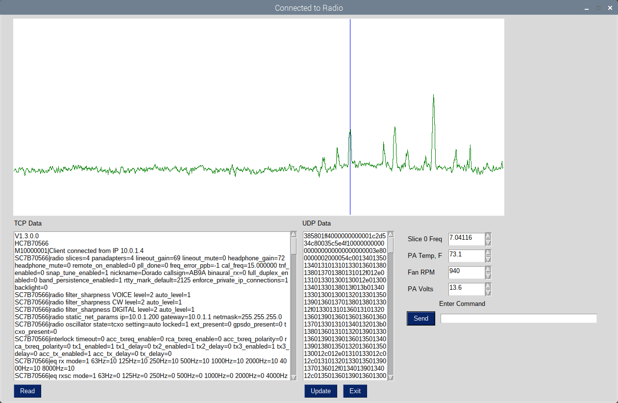
The "TCP Data" scrolling window is the cumulative data received over the TCP Port. It updates when the Read button is pressed.
The "UDP Data" scrolling window captures one Vita-49 packet every time the update button is pressed. And, it holds it for examination, until the update button is pressed again.
The spectral display is updated every time the UDP port captures a spectral display Vita-49 packet. Clicking the mouse inside the spectral display window tunes Slice Receiver 0 to the appropriate frequency.
Inside the "Slice 0 Freq" box you can read the Slice frequency.
The PA Temp, Fan RPM and PA Volts boxes are an exercise in reading and displaying the meter values.
The "Enter Message" box allows me to compose and send an API command to the radio.
This learning tool allowed me to study the data flowing to and from the radio. And, get comfortable with the process. But, when I put the display in free run mode, the update rate of the spectral display noticeably lagged behind the audio in the headphones. So to move to a realtime control surface, I needed something faster.
Writing a Realtime GUI:
The Python and "C" programming languages each have their pros and cons. But, Python is an interpreted language and "C" is a compiled language. Compiled code generally executes faster than interpreted code. So, I started looking for a GUI programmed in "C", that would run on a Raspberry Pi 4. What I found is GTK3+:
GTK3+ websiteThe basic idea of an event driven GUI is that when the user pushes a button or moves a control or the network connection receives data, an event is created. The GUI detects the event and sends a signal to the program (something changed). The program then runs the appropriate software function to handle the event. The concept is simple. The implementation can be challenging:
Example Audio Volume Control:
- Create horizontal scale widget, named "audio_volume"
    GtkWidget *audio_volume = gtk_scale_new_with_range(GTK_ORIENTATION_HORIZONTAL,0,100,1);
    gtk_scale_set_draw_value(GTK_SCALE(audio_volume), FALSE);
    gtk_widget_set_size_request (audio_volume, 150, 20);
gtk_box_pack_start (GTK_BOX (box19), audio_volume, FALSE, FALSE, 0);
g_signal_connect (audio_volume, "value-changed", G_CALLBACK (read_audio_volume), NULL);
    void read_audio_volume(GtkRange *range){
    char command[128];
    int len;
    byteswritten = 0;
    int slice_num;
    gdouble val = gtk_range_get_value( range );
    if(slice_A->active){
	slice_num = 0;
	sprintf(command, "CD%i|audio client 0 slice %i gain %d \n", cmd_num, slice_num, (int) val);
	len = strlen(command);
	strncpy(tcpoutbuf, command, len);
	byteswritten = write(tcpsoc, tcpoutbuf, len);
	slice_A->audio_gain = (int)val;
	cmd_num++;
    }
    if(slice_B->active){
	slice_num = 1;
	sprintf(command, "CD%i|audio client 0 slice %i gain %d \n", cmd_num, slice_num, (int) val);
	len = strlen(command);
	strncpy(tcpoutbuf, command, len);
	byteswritten = write(tcpsoc, tcpoutbuf, len);
	slice_B->audio_gain = (int)val;
	cmd_num++;
    }
}
gboolean read_tcp (){
    tcpbytes = read(tcpsoc, tcpinbuf, TCPREADBUF);
    gtk_text_buffer_insert_at_cursor (buffer2, (gchar*) tcpinbuf, tcpbytes);
    char tcp_msg[256];
    int j = 0;
    const char delim[2]= "="; // string delimiter
    char *property;
    char *value;
    int int_value = 0;
    for(int i = 0; i < tcpbytes; i++){
	if (tcpinbuf[i] == 0x56){		// Version
	    while (tcpinbuf[i] != 0xA){
		tcp_msg[j] = tcpinbuf[i];
		i++;
		j++;
	    }
	    tcp_msg[j] = '\0';
	    printf("%s",tcp_msg);
	    printf("\n");
	} else if (tcpinbuf[i] == 0x48){	// Handle
	    j=0;
	    while (tcpinbuf[i] != 0x0A){	//  LF

.......... continue parsing tcp data ........
}
And so it goes for every button, slider and mouse click.
Modern HF Transceivers have so many controllable settings that the front panel would have to be 4 times the size to hold all the knobs and switches. So, manufacturers resort to multifunction controls and menu selections, to conserve front panel space. Laying out the GUI control surface from scratch allows me to prioritize it for my working preferences. But, there are eventually conflicts in screen real estate that require some hard tradeoffs. You'll notice in the screen shots that groups of controls or windows disappear and reappear, depending on the current operational selections.
FlexRadio's SmartSDR for Windows is a remarkable piece of software. I can appreciate the thinking and design decisions that they had to make, in order to put so much functionality into one on screen display. Kudos to the SmartSDR team.
I have so far only implemented a subset of the available controls. The GUI is a work in progress. Some placement of controls are thought through. And, some are arbitrarily placed for expediency, in order to proceed with the software development. Likewise some controls are hard coded instead of parsing them live. Again, in order to expedite software development. My intention is to go back and derive them from the radio's response messages, further down the log. Some of the GUI controls may eventually be removed from the screen and transferred to a physical panel control.
Parsing the Radio's TCP Port Messages:
In able to use the radio's persistence feature to initialize the controller, it is necessary to read TCP status messages, parse them and store the data. Then read the data and set the GUI controls to the value of the data received.
All of the messages and command responses received from the radio, over the TCP port, are printable plain text (ascii). They start with a specific letter (V, H, M, S, R) and end with a linefeed (0x0A).
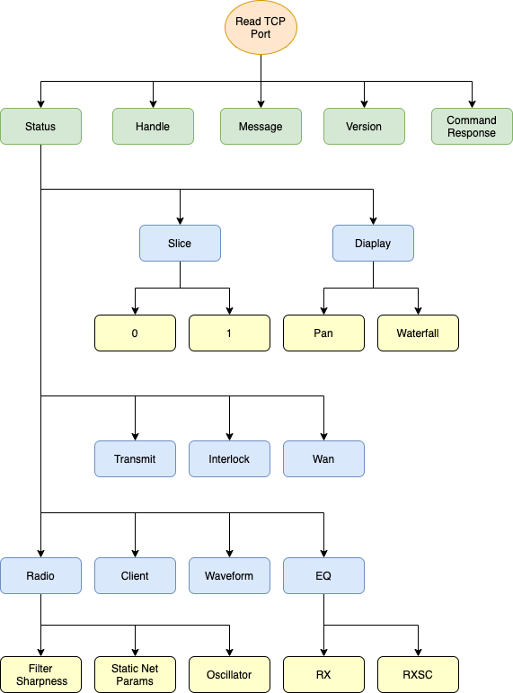
Parsing the individual messages requires traversing a decision tree until you reach the desired node (see Message Decision Tree diagram below). And then parsing the individual name-value pairs until you reach a linefeed (0x0A). For example, to parse the VFO frequency of Slice Receiver 0, the decision sequence would be:
Status -> Slice -> 0 -> RF_frequency=7.030000
Then parse: RF_frequency=7.030000 -> 7.030000
And, since 7.030000 is ascii characters and not a number, use the "C" function atof(value) to convert it to a number, of type double:
double slice_0_frequency = atof(7.030000);
Then continue to parse the slice_0 parameters (name-value pairs) until the terminating line feed (0x0A) is reached.
View the Status Message decision tree and parameter list.
Reading the UDP Port Data:
Once The TCP Port is connected to the radio, and the UDP Port has been is assigned, the radio begins sending data over the UDP Port. When data arrives at the controller's UDP Port, the GUI triggers an event indicating data is ready to be read and calls the software function "read_udp()". The "read_udp()" function queries the incoming Vita-49 packet, determines what type of data it contains (spectrum, waterfall, meter etc) and routes the data to the appropriate software routine:
gboolean read_udp(){

    udpbytes = read(udpsoc, udpinbuf, UDPREADBUF);

    if(udpbytes == 0){

	return TRUE;
    }

    classID = (udpinbuf[15] | udpinbuf[14] << 8);

        switch(classID){

	case 0x8002:  // meter

	    meter code here .....

	    break;

	case 0x8003:  // spectrum

	    spectrum code here ....

	    break;

	case 0x8004:  // waterfall

	    waterfall code here ....

	    break;

	case 0x8005:  // audio

	    audio code here ....

	    break;

	default:

	    printf("UNKNOWN CLASSID\n");
	}

    return TRUE;
}
Reading the USB Port Data:
Because the Raspberry Pi runs a version of desktop Linux. It does not handle hardware interrupts or real time external events. For example, the elapsed time between the time a VFO encoder knob is turned and the time the computer gets around to reading the encoder, allows the computer to intermittently miss steps. So, an Arduino microcontroller, that can handle real time interrupts, is used to capture encoder knob and switch events and send them to the Raspberry Pi over a USB Port.
The process is the same as the TCP and UDP Ports. When data arrives at the USB Port, the GUI triggers an event indicating USB data is ready to be read and calls the software function "read_usb()". "read_usb()" reads the USB input buffer, updates the appropriate GUI control and sends a command over the TCP Port to update the radio. The radio sends back a command response over the TCP Port indicating whether the command was processed successfully or not.
Observations on the TCP/IP API Wiki documentation:
I am working with version 2 software and relying on the Wiki documentation as a command reverence. And, I have observed the following discrepancies:
Some of the name/value pairs reported by the radio, over the TCP port, are read only. They are not settable in the category they are reported under. But, can be set in another category by a different variable name.
Example:
Parsing the TCP port data as Status --> Slice --> 0 -->
audio_gain=50
audio_pan=50
audio_mute=0
These are not settable under the Slice 0 commands.
They are set in the Audio Client under different names:
gain 50
pan 50
mute 0
Some of the name/value pairs reported by the radio, over the TCP port, are not listed in the API commands in the category they are reported. But, are settable there.
Example:
Status --> Slice --> 0 -->
rit_on=0
rit_freq=0
xit_on=0
xit_freq=0
Some range values in the Wiki are type floating point 0.0 --> 1.0 . But, the radio reports them over the TCP port as type integer 0 --> 100. Using the integer range works.
Example:
gain and pan under the Audio Client.
So, I have found that comparing the parsed TCP data with the Wiki documentation, along with experimentation is sometimes necessary.